Introduction
This specification describes the core components of the Software-Enabled Flash™️ (SEF) application programming interface.
The SEF API provides a simplified interface which abstracts away details of low-level flash memory device mechanics in such a way that allows hosts to interact with flash memory as though they were simple performance-optimized read/write devices. Hosts can make use of the SEF API to implement a custom Flash Translation Layer (FTL) or build SEF native applications bypassing all file systems in accordance with their application-specific requirements. The SEF API interfaces with SEF hardware Units. SEF Units are PCIe®️ based NVMe™️ devices, with certain SEF specific extensions to the NVMe command set. These extensions are separately defined as the SEF Command Set.
The SEF API addresses the following:
- Maintaining interface compatibility across flash memory generations
- Allowing host control over data placement to enable application-specific optimizations
- Providing mechanisms to enforce hardware isolation to support multi-tenancy
- Providing mechanism to allow control over housekeeping functions to support predictable latency
- Offloading computational burden from hosts via powerful API primitives
- Extension of flash memory lifetime due to intelligent automatic resource allocation
Figure 2.1 illustrates where the SEF library is located in the context of a traditional SSD-like application stack. The SEF Library accepts I/O requests from a host-defined FTL, and issues a set of commands. The SEF Unit translates this down to an appropriate set of flash memory-level operations.
Figure 2.1: SEF Library location in the system layer
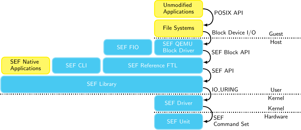
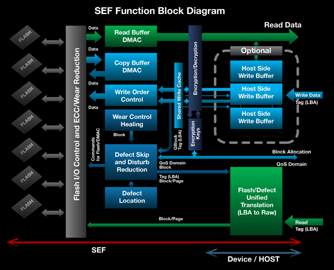
Figure 2.2 provides a detailed view of the system interface provided by the SEF API. SEF handles functionality including super block allocation, identifying and working around defective blocks, low-level flash memory I/O, scheduling, prioritization and other device-level concerns. The host layer in turn is responsible for implementing its own data placement strategy (including devising an appropriate logical-to-physical address mapping) as well as coordinating housekeeping functions such as wear leveling, garbage collection, and responding to asynchronous event notifications.
Figure 2.2: SEF Block Diagram